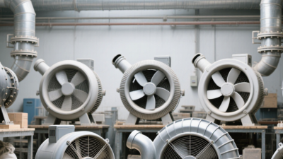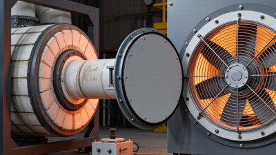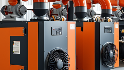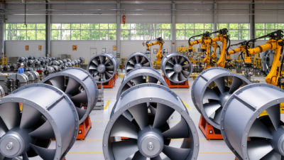
A Cooling Centrifugal Fan moves air by converting the rotating impeller’s energy into pressure and airflow. Unlike an axial fan, it pulls air into the impeller’s center and redirects it outward through a scroll-shaped housing. This compact arrangement supports cooling in electrical cabinets, data centers, HVAC equipment, battery systems, and industrial machinery. Picture the airflow entering through a narrow inlet, accelerating across curved blades, then leaving through a rectangular outlet. The sound and temperature of that process matter.
The market need is substantial. The International Energy Agency reports that electric motor systems consume roughly half of global electricity, including pumps, compressors, and fans. The U.S. Department of Energy also identifies fan and blower systems as important targets for industrial efficiency improvements. Meanwhile, Grand View Research has reported continued growth in the global HVAC equipment market, driven by urbanization, stricter efficiency expectations, and rising cooling demand. These figures do not describe every Cooling Centrifugal Fan application, but they show why fan selection deserves engineering attention.
Performance depends on more than advertised airflow. Engineers must evaluate static pressure, operating temperature, impeller design, motor efficiency, noise, filtration resistance, and duty cycle. A fan rated at 1,000 cubic feet per minute may perform poorly against a blocked filter. Small details matter. Poor inlet clearance can create turbulence, vibration, and unexpected energy use. In practice, the best selection balances cooling capacity, reliability, acoustic comfort, and maintenance access. The boundary is not always neat. A technically efficient fan can still disappoint when installation conditions differ from laboratory testing. Industry reports provide useful direction, but measured system data remains essential.
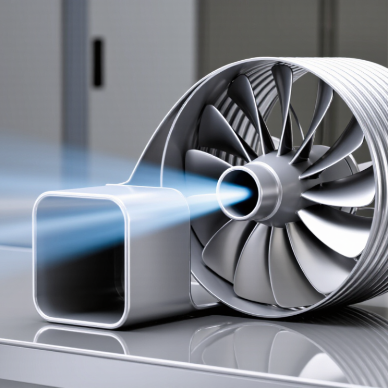
A centrifugal fan uses a rotating impeller to pull air inward and discharge it outward under pressure. Unlike axial fans, it handles resistance from coils, filters, dampers, and long ducts effectively. This pressure advantage suits air-handling units, packaged systems, and mechanical-room ventilation. The housing converts part of the impeller’s velocity into useful static pressure.
During cooling, the fan pushes air across a chilled-water or direct-expansion coil. Air leaves the coil colder and travels through supply ducts toward occupied rooms. The fan may also support heat rejection in selected condenser arrangements. The International Energy Agency’s The Future of Cooling report projects that global space-cooling demand could more than triple by 2050. That projection makes fan efficiency a practical concern. Cooling is not only about capacity.
Pressure, airflow, motor input, coil cleanliness, and control settings must be checked together. The U.S. Department of Energy’s Improving Fan System Performance sourcebook reports that fans consume about 15% of industrial electricity in the United States. Better sizing and variable-speed control can reduce waste.
Real installations are less tidy. A theoretical selection may look perfect on paper, yet fail in a dusty plant. Poorly tuned controls can create noise, drafts, or insufficient coil airflow. Commissioning measurements should determine the final setting.
What Is a Cooling Centrifugal Fan?
How Impellers Convert Motor Power into Airflow and Static Pressure
A cooling centrifugal fan uses a motor to spin an impeller inside a housing. Air enters through the impeller eye, near its center. The curved blades push air outward through centrifugal force. Air gains velocity as it leaves the blade passages.
The housing then guides this fast-moving air toward the outlet. Its expanding shape slows the air and converts part of its velocity into static pressure. This pressure helps air pass through filters, ducts, heat exchangers, and narrow vents. Without enough pressure, airflow can fall sharply, even when the motor is running normally.
Impeller design controls much of this performance. Diameter, blade angle, width, and rotation speed affect both airflow and pressure. A larger impeller can move more air, but it may also increase noise, vibration, and power demand. In practical testing, blocked filters often reveal the difference between free-air flow and useful cooling flow. The fan curve must meet the resistance of the complete system.
The model is useful, but incomplete. Turbulence, leakage, and poor alignment reduce real efficiency. I have found that a clean installation can matter as much as a stronger motor. Small clearances can change the sound and temperature noticeably. The best selection balances airflow, static pressure, energy use, and acceptable noise.
How impellers convert motor power into airflow and static pressure
A motor spins the impeller, which transfers energy to the air and drives it outward through the fan housing. At a fixed speed, a centrifugal fan typically produces higher static pressure at lower airflow and lower static pressure as airflow increases. Values shown are illustrative, not product specifications.
Key Ratings: 500–50,000 m³/h Airflow and 100–3,000 Pa Pressure
A cooling centrifugal fan moves air by drawing it into a rotating impeller. The impeller guides air outward into a casing, creating useful pressure. In practical installations, airflow may range from 500 to 50,000 m³/h. Pressure ratings commonly span 100 to 3,000 Pa. These figures describe working capacity, not a guaranteed output at every condition.
A fan delivering 500 m³/h suits a small control cabinet or compact equipment room. Larger systems may need 50,000 m³/h for heat exchangers, production halls, or ventilation networks. Pressure matters when air passes through filters, ducts, dampers, and grilles. A long duct with several bends can consume much of the available pressure. More airflow does not automatically solve that problem.
During commissioning, technicians should measure airflow, static pressure, motor current, and vibration. A clean filter can change performance noticeably. So can a partially closed damper. The stated rating may also reflect ideal test conditions. A neat calculation can still mislead. I have seen fans selected by airflow alone, then struggle against a restrictive duct system. Fan curves provide a more reliable selection method. They show how airflow and pressure interact at a specific speed. Leave practical margin, but avoid excessive oversizing. An oversized fan may waste energy, create noise, and make control unstable. Small details matter.
What Is a Cooling Centrifugal Fan?
Fan Types, Materials, and Motors with IE4 Efficiency Options
A cooling centrifugal fan moves air by drawing it into a rotating impeller and turning it outward. Its scroll housing then guides the airflow toward the outlet. In equipment rooms, this design handles duct resistance better than many axial fans. Backward-curved impellers usually offer strong efficiency and stable operation. Forward-curved wheels can provide high airflow in compact spaces. Radial-blade fans tolerate dust better, but they often create more noise and consume more power.
Material selection affects service life. Galvanized steel suits general indoor cooling systems and moderate humidity. Aluminum reduces weight and resists corrosion in many applications. Stainless steel is a safer choice near washdown areas or corrosive vapors, though it increases cost. Vibration, dust buildup, and poor alignment can damage any material. A clean housing is not enough. Technicians should inspect bearings, fasteners, and impeller balance during routine maintenance.
The motor deserves separate attention. An IE4 motor can reduce electrical losses compared with lower-efficiency designs, especially during long operating hours. Variable-speed control can reduce energy use further when full airflow is unnecessary. However, motor efficiency is not the same as total fan efficiency. Selection should include airflow, static pressure, temperature, duty cycle, and control method. A spreadsheet may suggest the perfect fan, yet field conditions can disagree. Small duct changes sometimes alter noise and power demand more than expected.
| Data Dimension | Option or Specification | Typical Technical Data | Cooling and Selection Characteristics |
|---|---|---|---|
| Fan Type | Backward-Curved Centrifugal Fan | Typical airflow: 1,000–100,000 m³/h Typical static pressure: 300–2,500 Pa Fan efficiency: approximately 70–85% |
Good energy efficiency and stable operation. Suitable for air-handling units, industrial ventilation, cooling systems, and clean-air applications. |
| Fan Type | Airfoil-Blade Centrifugal Fan | Typical airflow: 5,000–150,000 m³/h Typical static pressure: 500–2,000 Pa Fan efficiency: approximately 75–88% |
Designed for high-volume airflow with relatively low noise and reduced turbulence. Often selected for large HVAC and process-cooling systems. |
| Fan Type | Forward-Curved Centrifugal Fan | Typical airflow: 500–30,000 m³/h Typical static pressure: 100–1,200 Pa Fan efficiency: approximately 55–75% |
Provides compact construction and high airflow at low to medium pressure. Common in compact air-conditioning and equipment-cooling units. |
| Fan Type | Radial-Blade Centrifugal Fan | Typical airflow: 500–50,000 m³/h Typical static pressure: 500–4,000 Pa Fan efficiency: approximately 55–75% |
Robust design for higher resistance and particulate-laden air. Suitable for industrial exhaust, dust-handling, and process ventilation when properly configured. |
| Impeller Construction | Single-Inlet Impeller | Air enters from one side of the impeller; common diameter range: 200–1,250 mm | Simple layout and convenient maintenance. Suitable for most standard cooling and ventilation assemblies. |
| Impeller Construction | Double-Inlet Impeller | Air enters from both sides; airflow can be approximately twice that of a comparable single-inlet arrangement | Useful where high airflow is required without significantly increasing impeller diameter. Requires balanced inlet conditions. |
| Housing Material | Galvanized Carbon Steel | Typical sheet thickness: 1.0–3.0 mm Suitable for normal indoor and protected outdoor environments |
Cost-effective and widely used. Zinc coating improves resistance to ordinary atmospheric corrosion but is not intended for severe chemical exposure. |
| Housing Material | Powder-Coated Steel | Typical coating thickness: approximately 60–120 μm Common operating range: approximately −20 to 80°C, depending on coating system |
Provides improved surface protection and appearance. The coating specification should match humidity, temperature, and chemical conditions. |
| Housing and Impeller Material | Aluminum Alloy | Low-density construction with good corrosion resistance Density is approximately one-third that of steel |
Reduces rotating and structural weight. Often selected for lightweight equipment, mobile systems, and applications requiring moderate corrosion resistance. |
| Housing and Impeller Material | Stainless Steel | Common grades include austenitic stainless steels for humid or corrosive environments Typical sheet thickness: 1.0–3.0 mm |
Suitable for high humidity, washdown areas, and selected chemical environments. Material grade must be verified against the specific contaminants. |
| Motor Option | Three-Phase AC Induction Motor, IE3 | Typical power range: 0.75–315 kW Efficiency classification: IE3 under IEC 60034-30-1 |
Reliable and widely available. Suitable for fixed-speed or variable-speed operation when paired with an appropriately rated frequency inverter. |
| Motor Option | Three-Phase AC Induction Motor, IE4 | Typical power range: approximately 0.75–315 kW Higher efficiency than IE3 at comparable rated operating points |
Recommended where reduced electrical consumption and lower operating cost are priorities. Actual efficiency depends on motor size, load, speed, and operating conditions. |
| Motor Option | Electronically Commutated Motor | Typical power range: approximately 0.1–30 kW Integrated electronic commutation and speed control |
Efficient at part load and well suited to variable-airflow cooling systems. Requires compatible controls and attention to electromagnetic compatibility. |
| Motor Option | Permanent-Magnet Synchronous Motor | Typical power range: approximately 1–500 kW High efficiency over a broad operating range when correctly controlled |
Suitable for high-efficiency variable-speed applications. Requires a compatible drive and accurate motor-control settings. |
| Speed Control | Frequency Inverter | Typical adjustable frequency range: 10–60 Hz Actual minimum speed depends on motor cooling, bearing design, and fan stability |
Allows airflow and pressure to match the cooling demand. Variable-speed control can significantly reduce energy use at reduced airflow because fan power follows approximately the cube of speed. |
| Operating Temperature | Standard Air Temperature | Typical continuous air temperature: approximately −20 to 60°C Higher-temperature versions may require special bearings, insulation, or materials |
Verify the motor insulation class, bearing grease, seals, and structural clearances before operating above the standard temperature range. |
| Protection Rating | Motor Enclosure | Common protection levels include IP54, IP55, and IP56 Protection against dust and water depends on the specified IP rating |
Choose the enclosure according to humidity, dust, washdown exposure, and installation location. The fan housing and motor may have different protection levels. |
| Noise Performance | Operating Sound Level | Typical sound pressure level: approximately 55–85 dB(A), depending on size, speed, airflow, pressure, and measurement distance | Lower tip speed, optimized impeller geometry, flexible connections, vibration isolation, and acoustic treatment can reduce perceived noise. |
| Efficiency Consideration | Fan System Efficiency | Overall performance is influenced by fan aerodynamic efficiency, motor efficiency, drive efficiency, duct resistance, and control strategy | An IE4 motor improves motor efficiency, but the complete cooling system should be evaluated using the fan duty point, operating schedule, and total electrical input. |
What Is a Cooling Centrifugal Fan?
A cooling centrifugal fan moves air through a rotating impeller and redirects it outward. Its casing then guides airflow toward the outlet. Selection should begin with duty requirements, not fan size alone. Record airflow, static pressure, air temperature, density, noise limits, and available power. A small error in pressure estimation can produce weak cooling or excessive energy use.
AMCA 210 provides controlled laboratory methods for measuring fan airflow, pressure, power, and efficiency. Testing should use calibrated instruments, stable inlet conditions, and clearly defined operating points. Technicians should compare results at the required duty point, rather than relying on maximum airflow claims. Testing at several speeds also reveals how performance changes. Real installations are rarely perfect. Duct losses, filters, guards, and tight bends can shift the operating point.
ISO 13349 supports consistent fan terminology and classification. This matters when engineers specify impeller type, pressure terms, and operating conditions across different projects. A reliable selection sheet should state the test method, air density, rotational speed, efficiency, and tolerance. Inspect the curve carefully. A narrow safety margin may look efficient, but it can become unstable when filters load. I would also retest after installation, because field noise and airflow often differ from laboratory results. That gap deserves attention.