Choosing a Phosphate Ore Pump in 2026 starts with the slurry, not the catalog. Phosphate rock can arrive with sharp particles, changing solids concentration, and variable flow. A pump that handles clean water smoothly may struggle when abrasive solids enter the casing. Small details matter: particle size, pipe bends, suction conditions, and the hours between maintenance stops.
The U.S. Geological Survey’s Mineral Commodity Summaries 2025 estimates global phosphate-rock mine production at roughly 240 million metric tons in 2024. That scale signals sustained demand, but it does not determine the right pump for any one plant. The USGS report, prepared by phosphate-rock specialist Steven M. Jasinski, is useful for understanding the commodity backdrop. It is not a pump-sizing guide. A practical engineering takeaway is: “Select for the slurry at the impeller, not an idealized water duty point.” Treat that as a selection principle, not a verbatim Jasinski quotation.
Start with measured operating data. Record solids percentage, particle-size distribution, flow range, total dynamic head, and slurry temperature. Then compare wet-end materials, impeller design, and maintenance access against those conditions. Ask suppliers for references handling similar phosphate slurries, and check whether their performance claims match your duty cycle. Look closely at seal arrangements and wear-part lead times. Downtime is tangible.
There is no perfect specification sheet. Plant measurements can be incomplete, and ore properties can shift between faces or seasons. That uncertainty deserves attention, not a confident guess. The right Phosphate Ore Pump is the one proven against the actual duty, with assumptions stated clearly and verified in operation.
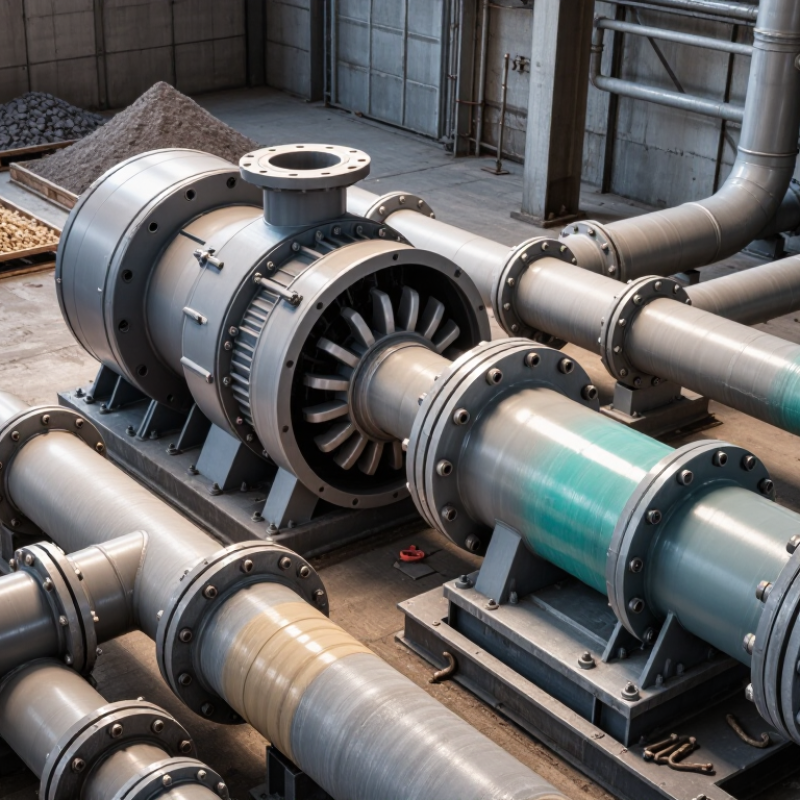
Phosphate ore slurry is not a uniform liquid. It carries mineral particles, water, and sometimes clay or other fine material. Particle size and solids concentration affect slurry density, settling, and flow resistance. A sample collected near the feed point may not represent conditions throughout a shift.
Pay attention to the largest particles, not only the average size. Coarse grains can increase wear and raise the risk of blockage, while fine clay may make slurry more viscous. Abrasive particles can erode wetted surfaces, especially where flow changes direction. Record solids content, pH, temperature, and flow variation under actual operating conditions. These details help engineers assess impeller passage, materials, and suction requirements. One lab sample can mislead. Recheck when the ore source changes.
Tips: Take samples during both steady operation and feed changes. Note whether solids settle in a bucket within minutes. Do not guess. Share particle-size data and the highest expected solids concentration with the pump supplier. Leave room for uncertainty; field conditions rarely match a tidy spreadsheet perfectly.

How to Choose a Phosphate Ore Pump in 2026?
Defining the Pump’s Flow, Head, and Operating Conditions
A phosphate ore pump should match the slurry duty, not just a catalogue figure. Start with the required flow rate, usually measured in cubic metres per hour. Then estimate total head, including elevation, pipe friction, bends, valves, and discharge pressure. A line carrying dense slurry may need more power than a water-based calculation suggests. Check the pump’s operating point against the system curve, not just its maximum capacity.
Operating conditions shape the choice. Record solids concentration, particle size, slurry density, temperature, and expected daily run time. Coarse particles can accelerate wear, while settling solids may restrict flow during slow operation. Include the suction pipe layout and available inlet pressure; inadequate suction conditions can cause vibration or unstable performance. Real installations are rarely perfect. A calculation may miss a partly blocked pipe or changing ore mix, so allow for measured variation rather than relying on one tidy estimate.
Tips: Measure flow and pressure on site where possible. Keep a sample of the slurry for solids and particle checks. Leave room for normal fluctuations, but avoid excessive oversizing. It sounds obvious, yet duty data is often incomplete. Recheck it before specifying the pump.
| Duty point or condition | Illustrative flow range | Illustrative total head | Operating conditions to define | Selection considerations |
|---|---|---|---|---|
| Mill discharge or coarse slurry transfer | 100–500 m³/h | 15–35 m | Solids concentration by weight; maximum particle size; particle shape; slurry density; presence of tramp material. | Check passage size and wear life against the actual particle-size distribution. Confirm the pump can operate across the expected flow range. |
| Beneficiation or process slurry transfer | 50–300 m³/h | 20–50 m | Solids concentration, particle-size distribution, pH, temperature, and whether the slurry contains process chemicals. | Select wetted materials for both abrasion and chemical compatibility. Use slurry properties—not water-only data—to establish the duty point. |
| Concentrate transfer | 30–200 m³/h | 20–45 m | Concentrate solids content, settling tendency, required delivery pressure, and continuity of operation. | Allow for start-up and restart conditions if solids can settle in the line. Verify the system curve and available suction conditions. |
| Tailings or low-pressure transfer | 100–800 m³/h | 10–30 m | Flow variation, solids concentration, pipeline length and elevation, settling risk, and discharge destination. | Calculate friction and static head at the required flow. Check minimum transport velocity and consider a variable-speed drive if flow varies materially. |
| High-head or long-distance transfer | 20–250 m³/h | 40–100+ m | Pipeline profile, pressure limits, slurry rheology, start-up sequence, and possible water-hammer or surge conditions. | Use a hydraulic system analysis to determine whether one pump or multiple stages are appropriate. Confirm maximum working pressure for all system components. |
| Suction and installation conditions | Record the minimum, normal, and maximum required flow. | Calculate from static lift, pipe losses, and required discharge pressure. | Liquid level, suction-pipe layout, temperature, altitude, entrained air, and available net positive suction head (NPSHa). | Compare NPSHa with the pump’s NPSH required, with an appropriate engineering margin. Avoid restrictive suction piping and air pockets. |
| Materials and wear life | Not a flow rating; base the choice on the measured slurry and duty. | Not a head rating; assess at the selected operating point. | Abrasive mineral content, particle size, pH, temperature, and maintenance access. | Compare suitable elastomer and metal wear-part options with the site’s chemical and abrasion conditions; use inspection history where available. |
The flow and head ranges above are illustrative screening examples, not universal phosphate-plant design values. Confirm the required duty using measured slurry properties, pipeline calculations, the pump curve, and site operating data. Total dynamic head includes static elevation, pipe and fitting losses, and required pressure at the destination.
Matching Pump Types and Materials to the Application
Start with the slurry, not the pump catalog. Phosphate ore varies in particle size, solids concentration, and water chemistry. A centrifugal slurry pump often suits continuous, high-volume transfer between process stages. For thick slurry, long pipelines, or controlled dosing, assess whether a positive-displacement design fits the duty. Check the full operating range, not just the normal flow rate. Pumps rarely work at one steady point.
Material choice depends on what wears and corrodes in your plant. Coarse particles can erode impellers and liners, especially at high slurry velocities. Replaceable wear parts may simplify maintenance. High-chrome metal can resist abrasion, while elastomers may handle some fine, less aggressive slurries. Neither is universally better. Confirm compatibility with actual pH, temperature, particle shape, and any dissolved salts. Small chemistry changes matter.
Match seals and clearances to the solids and maintenance conditions. Ask operators where leaks, blockages, or rapid wear appear; these observations can reveal more than a clean specification sheet. A neat spreadsheet can still be wrong. Compare predicted efficiency with site data, then check vibration, power draw, and wear after commissioning. Leave room for adjustment: ore properties shift, and early assumptions sometimes need revisiting.
A phosphate ore pump should be assessed against the slurry it will actually handle, not just its catalogue rating. Check flow, head, solids concentration, and particle size at the expected operating point. A pump running far from its efficient range can waste power and heat the slurry. That matters.
In field checks, compare energy use with wear patterns over several operating weeks. Record motor load, flow, and pressure, then inspect the impeller and liner for uneven thinning. Abrasive particles can shorten wear life, but choosing the hardest material is not always the answer; impact, corrosion, and repair time also affect the choice. A replaceable liner may cost more upfront yet reduce downtime. Sometimes it will not.
Maintenance needs should be practical for the site. Look for accessible inspection points, common wear components, and clear procedures for seal and bearing checks. Track vibration and temperature, but do not rely on sensors alone. A small leak or changing sound can be an early clue. Compare total operating cost, including electricity, spare parts, labor, and planned stoppages. No single pump suits every ore circuit, and estimates can miss real slurry variation. Leave room to reassess after commissioning.
In 2026, choosing a phosphate ore pump means checking the whole installation, not just the pump curve. Phosphate slurry can carry abrasive particles, so confirm solids size, slurry density, and expected flow before sizing. At site, check that suction pipework is short and well supported, joints are sealed, and the baseplate is level. Small alignment errors matter. The U.S. Department of Energy’s Improving Pumping System Performance sourcebook reports that pumping systems use nearly 20% of global electrical energy. Efficient operation starts with a correctly matched system.
Controls should respond to real process conditions. A variable-speed drive can help manage changing flow, but excessive speed reduction may cause settling in the line. Set alarms for low suction pressure, high motor current, and abnormal vibration. Verify these thresholds during commissioning; don’t rely on factory defaults. Supplier support matters, too. Ask for a duty-point assessment using your slurry properties, commissioning guidance, and documented spare-parts lead times. A polished curve is not a site test.
Tips: Before startup, flush the line and rotate the shaft by hand if the equipment procedure allows. Record pressure, flow, motor current, and vibration at a stable operating point. Keep those readings as a baseline. It is easy to overlook them when startup is busy, and that makes later troubleshooting harder. Recheck after process changes.