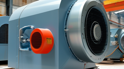
Choosing the right Kiln Centrifugal Fan is a practical decision with long-term consequences. The fan must move hot, dusty air reliably, often under demanding industrial conditions. A poor selection may cause unstable airflow, excessive noise, rising energy costs, or repeated maintenance.
Real-world assessment begins with kiln temperature, gas volume, pressure requirements, dust concentration, and operating hours. These details should come from measured process data, not rough estimates alone. Fan materials also deserve close attention. High-temperature alloys, reinforced housings, and suitable shaft seals can improve service life. However, stronger materials do not automatically solve every problem.
Look closely at the impeller design. Blade shape affects efficiency, wear resistance, and cleaning needs. A backward-curved impeller may reduce power demand, while a radial design can handle heavier dust loads. The correct choice depends on the kiln process. There is no universal answer.
Installation conditions matter, too. Space around the fan, duct direction, vibration control, and access for inspection can influence performance. A technically excellent fan may still perform poorly with an unsuitable duct layout. That point is easy to overlook.
Reliable selection should involve documented performance curves, verified testing, and advice from experienced manufacturers or engineers. Ask for data at the actual operating point. Marketing figures alone are not enough. A neat calculation can still mislead.
This guide examines the main factors behind a dependable Kiln Centrifugal Fan selection. It also considers efficiency, durability, maintenance, safety, and total ownership cost. Some assumptions may need revision after site testing. That is normal. Careful review leads to better decisions.
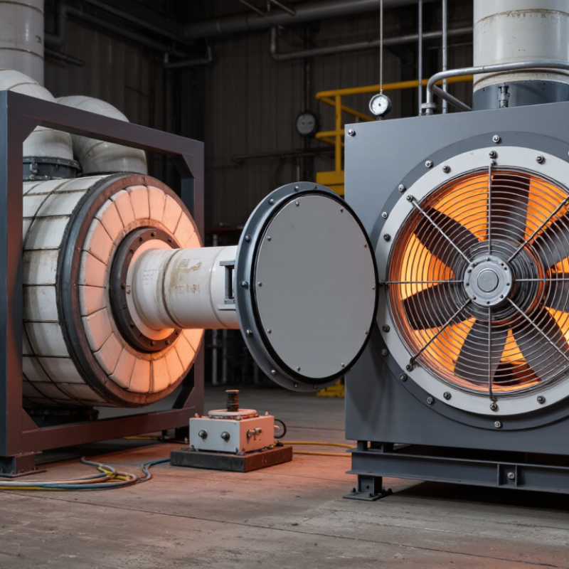
How to Choose the Right Kiln Centrifugal Fan?
Define Kiln Duty: Gas Temperature, Flow Rate, Pressure, and Dust Load
Kiln duty begins with measured gas conditions, not a catalogue airflow. Record temperature at the fan inlet, including start-up peaks. The U.S. EPA AP-42, Chapter 11.6, describes cement kiln systems with gas temperatures commonly exceeding 300°C. However, each process differs. A preheater kiln, lime kiln, and rotary dryer can produce very different profiles. Use actual operating data whenever possible. A neat spreadsheet can still lie.
Specify flow at the real inlet temperature and pressure. Standard cubic metres per hour cannot replace actual volumetric flow. Gas density changes sharply with heat. Pressure also needs clarity. State static pressure, total pressure, and whether the system operates under negative draft. The U.S. Department of Energy’s Fan System Assessment Tool guidance recommends checking the complete system curve, rather than selecting a fan from airflow alone. Allow for duct losses, filters, dampers, and future fouling. Dust matters too. EPA AP-42 identifies particulate emissions as a major kiln-control concern. High dust loading can erode impellers and imbalance rotating parts.
Tips: Measure at several production rates. Log the highest temperature, not only the average. Ask for dust particle size and concentration. Include cleaning intervals. I would also challenge the margin: excessive oversizing can create unstable control and wasted power. Field conditions are rarely perfect. That is exactly why commissioning data deserves more trust than assumptions.
Choosing a kiln centrifugal fan starts with measured airflow, pressure, temperature, and operating speed. Guesswork becomes expensive near the kiln’s maximum temperature. The affinity laws provide a practical starting point:
Here, Q means airflow, ΔP means pressure, P means shaft power, and N means rotational speed.
Suppose a test fan delivers 10,000 m³/h at 900 rpm and 1,200 Pa. Raising speed to 1,080 rpm gives an estimated airflow of 12,000 m³/h. Pressure becomes about 1,728 Pa, calculated as 1,200 × 1.2². Shaft power rises to about 1.73 times the original value. That increase is easy to underestimate. Check the motor carefully.
These relationships assume the same fan geometry, gas density, and operating conditions. Kiln exhaust can be hot, dusty, and less dense than room air. Therefore, convert performance data to the actual gas temperature and elevation before selecting the fan. Confirm the duty point against the system resistance curve, not only the fan catalogue.
I once focused on airflow and overlooked pressure loss across a dirty filter. The fan met the volume target, but the kiln draft remained unstable. That mistake showed why measurements matter more than attractive calculations.
Allow reasonable capacity for fouling, but avoid excessive oversizing. An oversized fan may waste power, increase noise, and disturb combustion control. Record actual temperature and pressure during commissioning, then compare them with the design assumptions.
How to Choose the Right Kiln Centrifugal Fan?
A kiln fan handling 250–600°C gas needs more than a standard carbon-steel casing. Confirm the actual inlet temperature, dust concentration, gas chemistry, and startup conditions. Kiln gas can heat the casing unevenly, causing distortion before the average temperature appears dangerous. Carbon steel may suit moderate temperatures, but higher ranges often require heat-resistant stainless steel or nickel-alloy components. Material selection must follow the real temperature profile.
A stainless casing alone is not enough. Abrasive dust can erode the impeller leading edges, blade backs, and scroll inlet. ASTM G65 measures abrasive wear through volume loss, reported in cubic millimetres. Its results help compare materials, but they do not predict exact kiln service life. Use replaceable wear plates, hardened blade surfaces, or thicker high-strength sections where dust strikes directly. Watch the joints.
AMCA Publication 204 links fan balance quality with vibration control, while ISO 14694 provides industrial fan vibration guidance. Specify dynamic balancing after any wear coating or repair. Keep bearings outside the hot gas path, and use a shaft design that limits heat transfer. Insulation can help, but trapped heat may create another problem. I would not select a fan from gas temperature alone. A 600°C design may still fail quickly if the dust is highly erosive, chemically reactive, or unevenly distributed. Verify the material choice through sampling, erosion testing, and operating records.
| Material / Construction | Typical Continuous Gas Temperature | Approx. Density (kg/m³) |
Thermal Expansion (10⁻⁶/K) |
Performance in Abrasive Dust | Recommended Fan Parts | Selection Notes | |
|---|---|---|---|---|---|---|---|
| Relative Abrasion Resistance | Dust-Service Suitability | ||||||
| Carbon Steel, Low-Alloy Grade | 250–400°C | 7,850 | 11–13 | Moderate | Suitable with replaceable wear liners | Casing, frame, shaft, and impeller for moderate-temperature service | Economical option below approximately 400°C. Use a high-temperature coating or abrasion-resistant liners where dust loading is high. |
| Abrasion-Resistant Steel Liner | 250–350°C | 7,700–7,850 | 11–13 | High | Very suitable for coarse mineral dust | Replaceable inlet liners, scroll liners, and impeller wear plates | Improves wear life but can become brittle or lose hardness at elevated temperatures. Avoid using it as the sole material above its verified service limit. |
| Weathering Steel | 250–400°C | 7,850 | 11–13 | Moderate to high | Suitable for dry, moderately abrasive dust | External casing and structural components in dry gas systems | Offers improved atmospheric corrosion resistance, but the protective patina may not form in continuously wet or highly acidic gas. |
| Austenitic Stainless Steel 304 | 250–600°C | 7,900–8,000 | 17–18 | Moderate | Suitable when corrosion is more important than wear | Casing, inlet components, and clean-gas-side parts | Good oxidation and corrosion resistance. It is not inherently abrasion-resistant, so exposed impeller surfaces may need hardfacing or liners. |
| Austenitic Stainless Steel 316L | 250–600°C | 7,950–8,000 | 16–17 | Moderate | Suitable for corrosive, moderately abrasive dust | Casing and wetted or condensate-prone components | Higher resistance to chlorides and acidic condensate than 304. Cost and thermal expansion are higher than carbon steel. |
| Heat-Resistant Stainless Steel 310S | 450–600°C | 7,700–8,000 | 15–16 | Moderate | Suitable for high-temperature gas with moderate dust | Impeller, casing, expansion joints, and hot-gas-side shields | Offers strong oxidation resistance at high temperature. Abrasion protection is still required for heavy particle impact. |
| Heat-Resistant Cast Alloy | 450–600°C | 7,500–8,100 | 10–14 | High | Suitable for hot, coarse, and erosive dust | Impeller blades, wear zones, and hot-side inlet sections | Maintains strength and oxidation resistance at elevated temperature. Confirm casting quality, weldability, and thermal-shock resistance before use. |
| Ceramic or Tungsten-Carbide Wear Overlay | 250–600°C subject to binder and application |
2,500–15,600 | 4–9 | Very high | Best for localized particle-impact zones | Blade leading edges, inlet cones, scroll cutoffs, and replaceable liners | Use as a wear layer over a ductile base metal. Check adhesion, thermal-expansion mismatch, impact loading, and maximum coating temperature. |
How to Choose the Right Kiln Centrifugal Fan?
For kiln applications, airflow and pressure must be verified under AMCA 210 test standards. This standard provides a controlled method for measuring fan performance, including airflow, pressure, power, and efficiency. Ask for test data that clearly identifies the operating point. A single maximum airflow number is not enough.
Check whether the reported pressure is static or total pressure. The difference can affect fan selection significantly. Confirm the test conditions, air density, temperature, speed, and measurement uncertainty. Kiln systems often handle hot, dusty air, so laboratory results may require careful correction. A catalog curve can look convincing. It may still miss your actual duct resistance.
Tips: Compare the required airflow and pressure with the fan curve at the real operating speed. Leave a reasonable margin, but avoid excessive oversizing. An oversized fan may waste energy, create noise, and operate away from its best efficiency point. Review impeller material, bearings, sealing, and maintenance access for the kiln environment.
Request AMCA 210-based documentation from the supplier, not only a general performance chart. Check whether the tested configuration matches the proposed fan, including inlet conditions and outlet arrangement. Small connection changes can influence pressure readings. I have seen projects focus on airflow while overlooking system resistance. That shortcut becomes expensive later. Recheck the calculation when kiln temperature or production load changes.
Choosing a kiln centrifugal fan requires more than comparing airflow and motor size. Measure the kiln’s real operating point: airflow, static pressure, temperature, and dust loading. U.S. Department of Energy guidance reports that fan systems can consume 15–20% of industrial electricity. Small efficiency losses become expensive during continuous firing. Select a fan near its best-efficiency point, then verify motor efficiency, variable-speed control, and leakage around ducts.
Noise needs equal attention. Compare sound power levels, not only sound pressure at one distance. A practical test should record readings near the operator position and beside the kiln casing. ISO 13349 provides consistent fan terminology and classification, but it does not establish a universal efficiency or noise limit. Do not treat compliance language as performance proof. Ask for test conditions, tolerances, and temperature corrections. My experience suggests that a quiet fan can still create harsh tonal noise when it operates far from its design point.
Tips: Build a short risk checklist under EN 12100. Identify hot surfaces, rotating parts, dust release, vibration, and unexpected restart. Use guards, lockout provisions, emergency stopping, and thermal monitoring. EN 12100 emphasizes risk assessment and risk reduction; it is not a substitute for detailed machine testing. The U.S. DOE sourcebook also recommends checking system effects, because elbows, dampers, and undersized ducts can waste energy. Leave room for reflection: a technically efficient fan may be a poor choice if maintenance access is unsafe or cleaning repeatedly changes its operating point.
Comparing efficiency and noise while applying ISO 13349 and EN 12100 principles
The chart uses representative engineering values at comparable operating points. Airfoil and backward-inclined fans generally provide higher efficiency, while forward-curved and radial-blade designs may be selected for different pressure, dust-loading, or robustness requirements. Actual sound pressure depends on speed, system resistance, installation, and distance from the fan.
ISO 13349 provides fan terminology and classification guidance; it does not set a universal efficiency or noise limit. EN 12100 requires a documented machinery risk assessment and risk reduction process, including guarding, access control, emergency stopping, residual-risk information, and verification of protective measures.